
Identification and Sensing Hardware for Utilities
Evaluate identification devices, utility sensors, gateways, and edge hardware for reliable asset data across electric, water, and gas infrastructure.
Explore Hardware ↘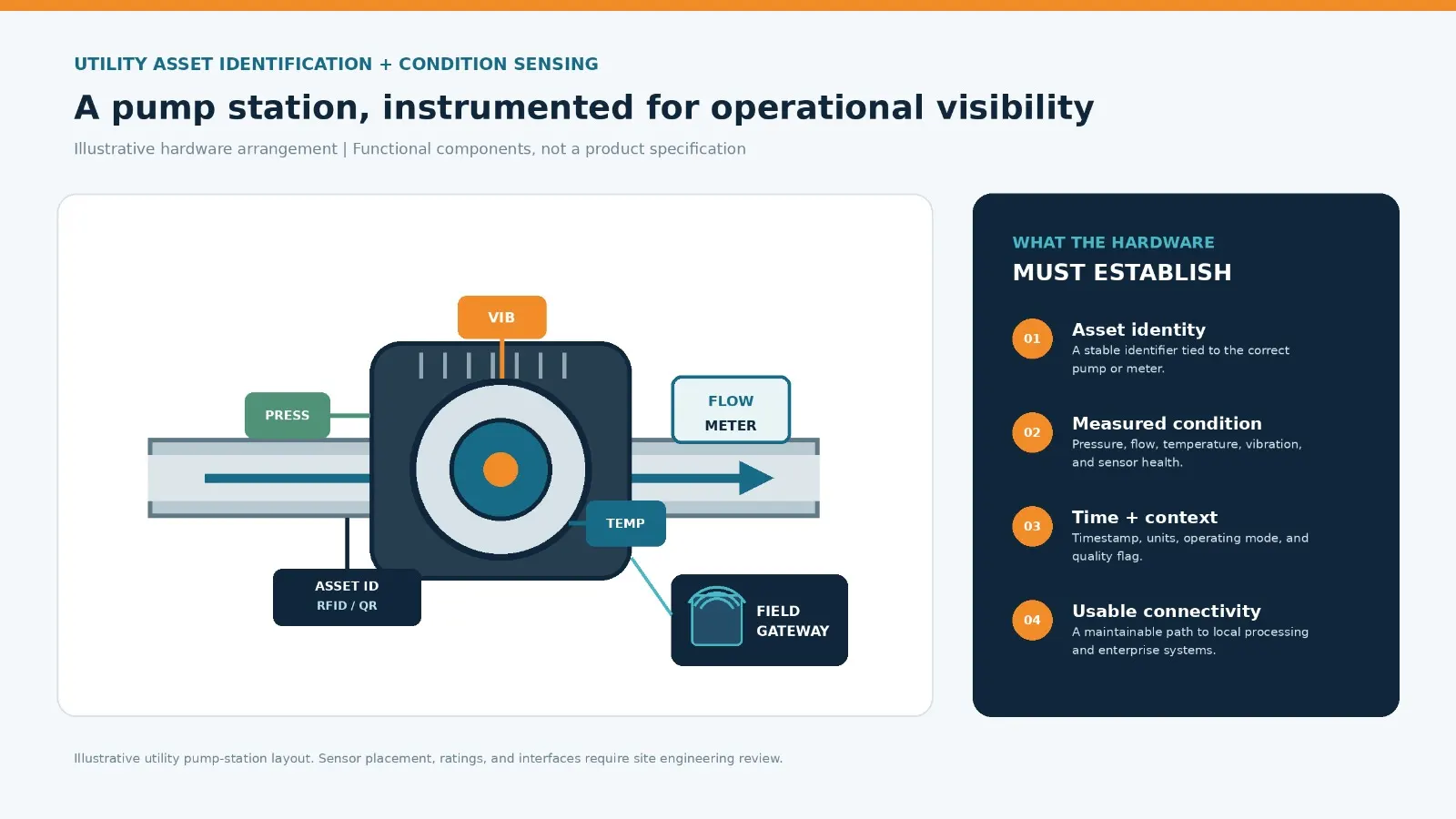
Reliable Operations Begin with Trusted Asset Information
Reliable utility operations depend on knowing which asset is being observed and whether its measured condition is trustworthy. Identification devices, sensors, gateways, and edge computers provide the physical data layer for monitoring distribution networks, substations, pumping facilities, water treatment assets, and other utility infrastructure.
Hardware selection should begin with the operational question, the asset environment, and the information required by the people responsible for inspection, operations, and maintenance.
A meter reading, a pump vibration measurement, and a substation temperature observation have different installation, power, communications, and validation requirements. These components should be considered as parts of a complete operational system rather than as isolated devices.
Identify Utility Assets and Field Equipment
Identification hardware links a physical asset to its maintenance history, location, measurements, and operational records. The appropriate method depends on whether a utility needs to identify a fixed network asset, read a meter, locate a mobile maintenance resource, or document an inspection.
Tags, Labels, and Asset Identifiers
Radio-frequency identification (RFID) tags can support non-line-of-sight identification when readers and tags are positioned within a suitable read zone. Passive tags do not require an onboard battery, while active tags use a power source to support functions such as periodic transmissions.
Tag selection must account for mounting material, metal surfaces, enclosure design, temperature, moisture, radio interference, read distance, and maintenance access.
Barcodes and quick response (QR) labels offer a visual identification option for assets that technicians can approach and scan. Their usefulness depends on label condition, visibility, lighting, and a deliberate scan.
Readers, Anchors, and Cameras
Fixed RFID readers can capture tagged assets at selected access points or maintenance areas. Bluetooth Low Energy (BLE) receivers and ultra-wideband (UWB) anchors can contribute to location workflows when the required coverage, tag behavior, accuracy, and infrastructure density have been established through a site survey.
Cameras can read visible identifiers, inspect equipment condition, or capture evidence during a field visit. Their usefulness depends on line of sight, image resolution, lighting, weather protection, mounting stability, and controls for access to images that may contain people or sensitive site information.
Select Sensors for Utility Operating Conditions
Sensors convert physical conditions into measurements that can support operational awareness and maintenance decisions. Select each instrument against a defined variable, measurement range, installation point, sampling requirement, and acceptable uncertainty.
Electrical Measurements
Voltage, current, frequency, power, and power quality indicators for relevant electrical assets. Instrument transformers and metering interfaces must be selected and installed under applicable engineering and safety requirements.
Temperature
Equipment, enclosure, bearing, transformer, or ambient temperature, using a measurement method suited to the expected range, response time, and installation point.
Pressure and Flow
Pressure and flow measurements in water and gas networks, pumping systems, and treatment processes. Wetted materials, pressure rating, fluid compatibility, flow profile, and installation geometry affect suitability.
Vibration and Acoustics
Condition indicators for rotating equipment such as pumps and motors, where sensor mounting, frequency response, operating speed, and baseline behavior are understood.
Level and Environmental Conditions
Tank or reservoir level, humidity, water quality, weather, or other site-specific variables where the measurement is relevant to the utility process.
Visual and Thermal Observations
Camera or thermal imaging inputs for selected inspection tasks. Image quality, viewing angle, emissivity assumptions for thermal measurements, and inspection conditions must be documented.
Connect Field Devices Through Gateways and Edge Hardware
Gateways collect data from field devices and provide a controlled path to local applications, edge computers, or approved enterprise systems.
Field Communication
Depending on the site, the design may use wired industrial networks, cellular connectivity, Wi-Fi, or other radio links. The selected interface must be confirmed against installed equipment and the utility’s network and cybersecurity requirements.
Local Data Processing
Edge hardware can filter, buffer, timestamp, or preprocess observations close to the asset. Local processing may be useful where connectivity is intermittent, response time is important, or only selected events should be forwarded.
Power and Installation
Confirm whether a device uses utility power, an instrument supply, battery power, or energy harvesting. Include surge protection, grounding, enclosure rating, cable routing, and safe maintenance access in the installation review.
Maintenance and Recovery
Edge computing does not remove the need for data-quality checks, secure configuration, time synchronization, device inventory, software maintenance, and recovery procedures.
Compare Hardware Against Site Requirements
Use the following selection framework for each asset class and installation location before procurement. It is not a compatibility statement or a list of approved UtilityGrid products.
| Selection Factor | Questions to Resolve | Evidence to Record |
|---|---|---|
| Operating Environment | Indoor or outdoor? Temperature, moisture, dust, vibration, corrosion, flooding, hazardous-area constraints? | Site conditions, enclosure requirements, environmental ratings, installation location. |
| Power | Available supply, backup, battery replacement access, energy budget? | Power source, expected load, maintenance interval, backup plan. |
| Placement and Coverage | Can the device read or measure the target reliably from the proposed location? | Site survey, mounting plan, coverage test, line-of-sight or radio constraints. |
| Measurement Quality | What range, accuracy, resolution, sampling interval, and calibration are required? | Instrument specification, calibration record, test method, quality flags. |
| Connectivity | Which physical and network interfaces are available and approved? | Interface details, network path, latency needs, buffering and outage behavior. |
| Serviceability | Can technicians inspect, replace, clean, recalibrate, or update the device safely? | Access plan, maintenance procedure, spares approach, device inventory. |
| Data Association | How will readings map to asset ID, timestamp, unit, operating mode, and source? | Data dictionary, identifier mapping, time synchronization, event-quality rules. |
Conceptual Hardware Arrangement for a Utility Pump Station
A pump-station monitoring workflow illustrates how identification and sensing components work together. The following is a conceptual bill of materials by function. It is not a procurement specification, a tested configuration, or a statement that UtilityGrid supports a particular device.
Design the Complete Measurement Path
The arrangement starts with asset identity and selected measurement points. Field acquisition, connectivity, installation, and verification must be considered together so that the resulting records can be interpreted in their physical context.
Quantities depend on the number of monitored assets, measurement points, and required redundancy.
Asset Identification
One durable asset label or RFID tag for each selected pump, motor, or meter, with a documented identifier mapped to the utility asset register.
Condition Measurement
One or more suitable pressure, flow, temperature, or vibration instruments selected for the measurement objective and equipment design.
Field Acquisition
Required signal-conditioning or input modules to collect selected instrument outputs, with isolation and electrical protection as required by engineering review.
Connectivity
One appropriately rated gateway or edge device to collect field observations and forward approved records over the site’s available network.
Installation and Verification
Mounting hardware, cabling, enclosure, power provision, commissioning checks, calibration evidence, and maintenance access appropriate to the site.
From Field Observation to Operational Data
A useful hardware installation produces records that downstream software can interpret without losing their physical context.
Preserve the distinction between the time a measurement occurred and the time it reached the receiving system.
Instrument or Identification Device
The physical device produces a reading or identification event.
Field Input or Reader
The field input module or reader receives the device output.
Gateway or Edge Node
The gateway or edge node collects, timestamps, buffers, or preprocesses observations as required.
Approved Network Connection
Records travel over the network connection approved for the site.
Data Ingestion and Asset Association
The receiving service processes the record and associates it with the correct asset and context.
Operational Application
Engineering or maintenance personnel use the information within the relevant operational workflow.
Validate Before Scaling Across the Network
A pilot should test the selected equipment under representative site conditions before extending it across a larger asset population. Include normal operation and relevant stress conditions, such as intermittent connectivity, low battery, sensor drift, obstructed reads, environmental exposure, and delayed maintenance.
Identification Performance
Required event completeness, missed reads, duplicate events, false associations, and time needed to reconcile exceptions.
Measurement Performance
Range and unit checks, calibration status, missing-data frequency, drift, noise, and agreement with an independent reference.
Communications Performance
Delivery delay, message loss, recovery after an outage, buffering behavior, and time synchronization.
Maintenance Impact
Installation effort, safe access, inspection frequency, battery or power servicing, replacement process, and technician workload.
Operational Usefulness
Whether the data reaches the correct asset record and supports a defined inspection, maintenance, or operations decision.
Field Sensing Across Electric Utility Infrastructure
Electric utilities may need to observe different conditions across substations, transformers, switchgear, overhead lines, underground distribution assets, and supporting facilities.
The appropriate sensor set depends on the asset and the maintenance question. Examples may include temperature at selected connection points, electrical measurements from approved metering interfaces, vibration on rotating auxiliary equipment, or visual observations during inspections.
For outdoor assets, mounting and communications design must account for weather exposure, electromagnetic conditions, physical access, line-of-sight limitations, and safe work practices.
Sensor installation on or near energized equipment must be planned and performed under the utility’s approved procedures by qualified personnel. This page does not prescribe live-line installation methods or universal sensor placements.
Field data should be associated with a unique asset record and inspection context. If an observation is uncertain, stale, or outside its validated operating range, the receiving workflow should make that limitation visible.
Start with the Asset and the Operational Question
A practical assessment starts with a defined asset class and a short list of decisions the resulting data should support. Identify the assets in scope, the measurements or identification events required, available power and communications, existing asset records, maintenance responsibilities, and the criteria for accepting pilot results.
Frequently Asked Questions
Considerations for evaluating identification and sensing hardware across utility infrastructure.
What hardware is used to identify utility assets?
Depending on the workflow, options include durable labels, barcodes, QR codes, RFID tags and readers, BLE devices, UWB anchors, and cameras. Selection depends on asset material, read distance, coverage, environment, power, and the required level of location or identity confidence.
Which sensors are relevant to utility infrastructure?
Common measurement categories include electrical variables, temperature, pressure, flow, vibration, acoustics, level, and selected environmental or visual observations. The correct instrument depends on the asset, measurement range, installation point, calibration requirements, and operational question.
Why are gateways and edge devices needed?
Gateways connect field devices to an approved network or application. Edge devices may perform local filtering, buffering, timestamping, or preprocessing, particularly where connectivity is intermittent or local processing is required.
Does UtilityGrid hardware work with every utility device or protocol?
No universal compatibility claim is made on this page. Device, protocol, interface, and network compatibility must be confirmed against the specific equipment documentation, site architecture, and a tested integration scope.
How should a utility validate identification and sensor hardware?
Define acceptance criteria before the pilot. Test event completeness, false associations, measurement quality, calibration, communications recovery, environmental suitability, maintenance effort, and whether the data is correctly linked to the asset record.