
The UtilityGrid Physical AI and AIoT Engines Architecture
Utility operations depend on accurate asset identity, trustworthy measurements, timely decisions, and controlled responses. UtilityGrid’s architecture organizes these functions into two related configurations: the UtilityGrid AIoT Engine™, which connects identification, sensing, and AI-supported decisions, and the broader UtilityGrid Physical AI Engine™, which adds a controlled path from an approved decision to physical action and independently checked results.
The architecture is intended to be adapted to the assets, operating procedures, data sources, and control boundaries of each utility environment. Examples may include substations, distribution networks, pumps, meters, and other infrastructure assets, subject to site requirements and technical validation.
Two Connected Architecture Layers
The UtilityGrid AIoT Engine™ provides the information and decision layer. It associates field observations with the relevant asset or event, captures operating measurements, and evaluates the resulting information. The three engines work together, but they perform distinct functions:
Identification Engine: associates observations and events with the correct asset, equipment item, location, or operational record.
Sensing Engine: acquires measurements such as temperature, vibration, pressure, flow, electrical values, and environmental conditions where relevant to the selected asset and use case.
AI Decision Engine: evaluates identity and measurement context to support anomaly review, risk prioritization, maintenance planning, forecasting, or recommendations. The selected decision method must be evaluated against representative operating data.
The UtilityGrid Physical AI Engine™ includes the AIoT layer and adds the Physical AI Action Engine. This additional layer connects an approved decision to an authorized operational response through suitable equipment interfaces, permissions, and safeguards. The action path is separate from the AIoT decision path; a recommendation or workflow request does not, by itself, constitute equipment control.
Physical AI Action and Verified Results
The Physical AI Action Engine receives an eligible decision output and manages the defined execution path. Depending on the application, this may involve a human-mediated task, a human-approved command, or a bounded automated action. The design must identify the target equipment, command interface, responsible authority, operating limits, and fallback behavior.
A command acknowledgment confirms that a command was received or accepted by an interface. It does not prove that the intended physical change occurred. Verification requires subsequent evidence from an independent observation of the asset or process, such as a relevant sensor reading, equipment state, or confirmed position. Outcomes that cannot be independently checked should remain marked as unverified.
Utility System Boundaries and Data Flow
A deployment design should make the boundary between field equipment, edge processing, enterprise services, users, and external systems explicit. The exact arrangement depends on the site, available interfaces, latency requirements, connectivity, cybersecurity rules, and operating responsibilities.
Field devices and operational sources
Potential inputs include asset registers, equipment identifiers, meter readings, sensor measurements, inspection observations, equipment status, and relevant operational records. The data model should preserve the relationship between each observation and its source asset. Device selection and measurement plans require review against installation conditions, environmental exposure, calibration needs, and maintenance access.
Edge, server, and cloud processing
Edge devices or gateways may collect and buffer field data, apply local processing, and exchange information with server or cloud services where the deployment design permits. Processing location should be selected according to response-time needs, network availability, data governance, maintainability, and the consequences of losing connectivity. This architecture does not imply that every deployment uses every processing tier.
Enterprise and operational interfaces
Integration may involve asset-management, maintenance, work-management, supervisory control, or other operational systems. Each interface should define ownership, permitted read and write operations, identifiers, event mapping, time handling, versioning, and error behavior. Compatibility with a named system or protocol should be confirmed through an interface assessment and testing rather than assumed.
People, authority, and oversight
Operations personnel, control-room operators, maintenance planners, engineers, and system administrators may have different responsibilities. Role-based access, approval records, audit logs, and clear escalation paths help ensure that decisions and commands remain within assigned authority. Human override and recovery procedures should be defined before any physical action is enabled.
Cross-Cutting Controls
Identity and data quality: retain asset identifiers, source information, timestamps, units, and quality flags. Handle missing, duplicate, delayed, stale, and conflicting observations explicitly.
Timing and event order: distinguish event time from ingestion time, account for clock differences, and document acceptable delays for each workflow.
Access and cybersecurity: define authenticated users and devices, least-privilege permissions, protected interfaces, credential handling, and auditable changes.
Availability and recovery: specify buffering, retry behavior, timeout handling, safe fallback states, and recovery after network or service interruption.
Human authority and safety: define approval requirements, manual override, operating limits, and the relationship to independent protective systems.
Outcome verification: retain the decision, command, acknowledgment, and subsequent observed state as distinct records.
Architecture Visual
The diagram distinguishes the nested AIoT information and decision layer from the larger Physical AI architecture. The Physical AI Action Engine sits within the outer Physical AI boundary but outside the AIoT boundary.
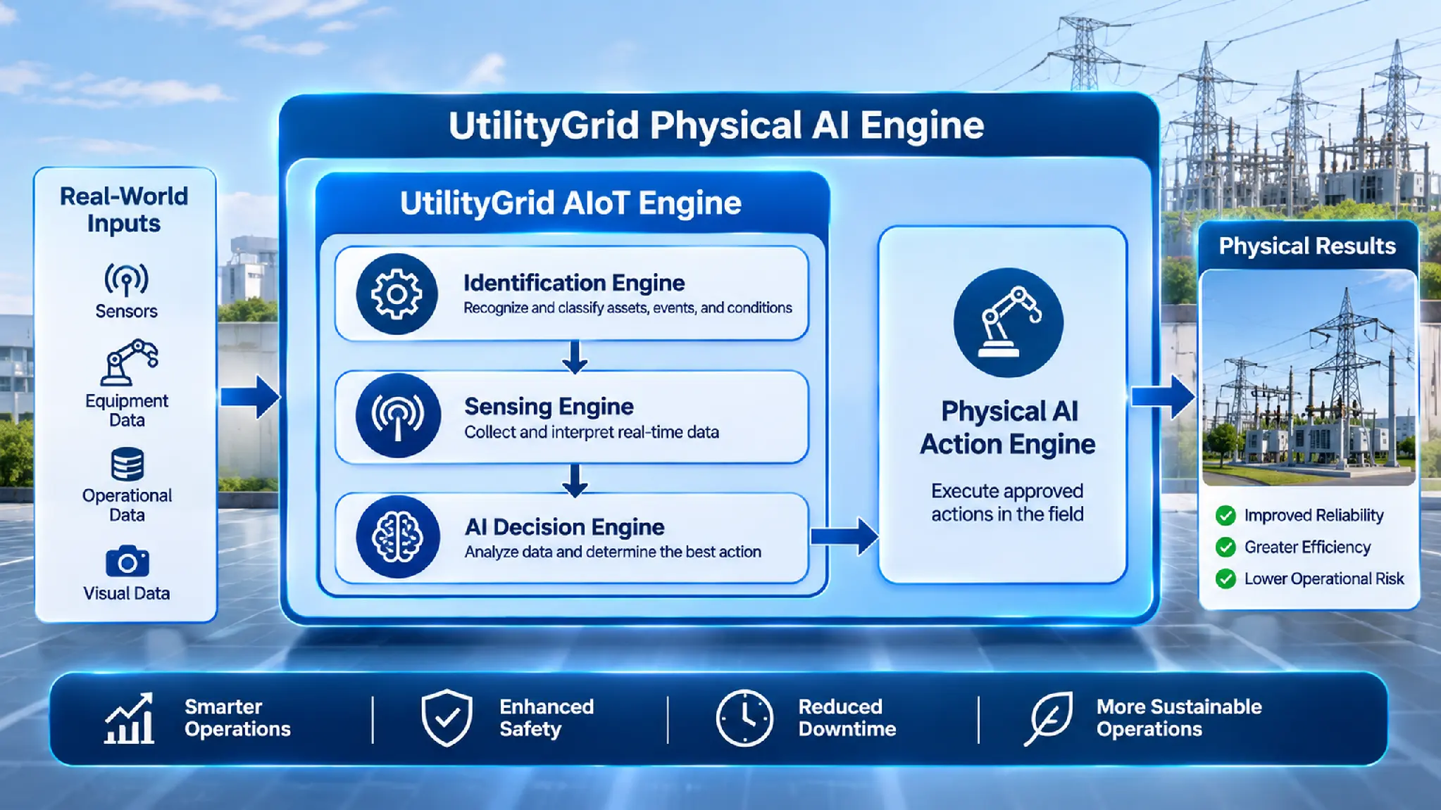
Utility Network Physical AI Architecture and Operational Action Flow
The visual shows the UtilityGrid AIoT Engine™ nested within the UtilityGrid Physical AI Engine™. Identification, sensing, and AI decision functions are arranged vertically inside the AIoT boundary. The Physical AI Action Engine sits outside that inner boundary and receives the decision output before producing physical results. The nested layout distinguishes information processing from authorized physical execution.
Example Data Contract
A shared data contract helps preserve traceability across observation, decision, command, and outcome records. The following fields are a proposed minimum example for design discussion, not a claim that a production interface or connector is already implemented.
| Field | Purpose | Handling note |
|---|---|---|
| asset_id | Identifies the utility asset associated with the record. | Use a stable identifier mapped to the authoritative asset register. |
| event_time | Time the physical observation or event occurred. | Include timezone or use a documented UTC convention. |
| ingestion_time | Time the platform received the record. | Keep separate from event_time to expose delivery delay. |
| units | Defines the unit for each numeric measurement. | Use an explicit unit and validate expected ranges. |
| quality_flag | Indicates measurement or record quality. | Define values for valid, missing, stale, estimated, or suspect data. |
| model_version | Identifies the model or decision logic version. | Record the exact version used to produce the decision. |
| decision_id | Links input observations to a decision record. | Keep decision output and confidence or uncertainty metadata distinct. |
| command_id | Links an authorized command to its decision. | Record authorization, dispatch, acknowledgment, and status separately. |
| observed_outcome | Captures the independently observed result after action. | Do not treat command acknowledgment as proof of physical completion. |
Evaluation and Implementation Considerations
Before selecting an implementation, define the operating question, asset scope, users, source systems, data quality requirements, response-time expectations, and consequences of an incorrect decision or action. Establish a credible baseline and select measures that match the intended workflow.
- For identification workflows, assess event completeness, missed or duplicate observations, incorrect asset associations, and reconciliation effort.
- For sensing and condition workflows, assess measurement coverage, calibration requirements, missing-data behavior, detection delay, and false-alert workload.
- For decision workflows, assess performance against representative operating conditions, uncertainty handling, drift, escalation, and human review.
- For physical action workflows, assess authorization failures, rejected commands, timeouts, override events, recovery behavior, and independently verified outcomes.
Explore the UtilityGrid Engine Architecture
Explore the component pages to understand each engine’s role and its implementation requirements:
Discuss Your Utility Environment
Discuss your assets, operational workflows, data sources, integration requirements, and authority boundaries with UtilityGrid. A requirements discussion can help establish which parts of the architecture are relevant and what evidence a site-specific evaluation should produce.